[h=1]Casing Design Overview – Overall Process of How To Do Casing Design in Oil and Gas Industry[/h]
After understanding the basic of each casing string run in oil wells, we will go into casing design overview. This article will give you general ideas of casing design.
 [h=2]Casing Design Objectives[/h]
After understanding the basic of each casing string run in oil wells, we will go into casing design overview. This article will give you general ideas of casing design.
The items below are design objectives for well constructions which drilling engineers must consider.
[*=left]Design must meeting production strategies.
[*=left]Design must provide mechanical integrity based on anticipated load cases which will be encounter during life time of the well.
[*=left]Cost of well must be economic.
[*=left]Design must provide ways to be able to plug and abandon the well at the end of wells life.
These objectives are generic and your wells may have additional objectives based on business needs.
[h=2]Data Required for Casing Design[/h] The following items are information require for casing design.
- [h=3]Production Information[/h]
o Type of packer fluid
o Density of packer fluid
o Type of reservoir fluid
o Expected flow rate, pressure, temperature of the well
o Sour gas (H2S, Co2)
o Maximum production load case
o Completion strategies
- [h=3]Geological Data[/h]
o Pore pressure
o Fracture pressure
o Formation temperature
o Formation type and structure
o Plan for logging programs
o Location of problematic zones as possible loss zones, high permeable zones, unstable zones, shallow gas hazard, fresh water zones, sour gas (H2S, CO2) zones, etc
- [h=3]Directional Data[/h]
o Geologic targets
o Surface location
o Anti-Collision issue
- [h=3]Production plan[/h]
o Size of casing and tubing met required production rate
o Completion equipment (packer, SCSSV, gas lift valves, etc) planned to run into the well
- [h=3]Government regulation[/h]
o Each country has different requirement for drilling oil wells.
- [h=3]Equipment supply and logistics[/h]
o International or local suppliers for casing
o Logistics and tax for equipment
[h=2]Design Phases[/h] There are two phases of design. The first on is a preliminary design and the second one is a detailed design.
[h=3]Preliminary Design Phase[/h] After gathering information required, you will do the first phase of casing design. The preliminary design will give you all scopes of the project (well construction plan). The following scopes are results from this phase.
[*=left]Casing setting depth and number of strings – The following factors used to determine casing setting depths.
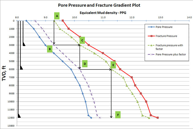
o Pore pressure and fracture gradient – Based on the pore pressure and the fracture gradient of the well, you will be able to determine how many strings required and where each string needs to be set. There are two approaches which are top down design and bottom up design. We will go into details of this topic later on.
o Differential sticking zones – potential sticking formations should be cased off before going deeper because the deeper depth requires higher mud weight which will result in more serious of pipe stuck issue.
o Wellbore stability – this is the same concern as the differential sticking. Right type of mud and weight will minimize this issue.
o Formation pressure / fracture gradient prediction uncertainty – drilling into unknown areas has a lot of uncertainty regarding pore pressure / fracture gradient prediction. Therefore, additional string must be considered to run as a contingency string.
o Directional concern – Typically casing is set after a building section of the well in order to mitigate a key seat issue while drilling deeper.
[*=left]Drilling fluid program – drilling fluid weight is the most critical factor in the casing design. Mud weight should be sufficient enough to drill to planned depth without fracturing formation at shallower depth. Moreover, drilling mud for each section needs to meet drilling objectives as hole cleaning, wellbore stability, formation evaluation, minimizing formation damage, etc.
[*=left]Drilling equipment needed – drilling equipment is one of the factors which need to take into account carefully. You should ask yourself about drilling equipment:
o What is the specification of the drilling rig?
o Can the rig work with the casing plan?
o Does the rig have enough power to provide hydraulic power to downhole tool, clean the hole, etc?
o Do we have the well control equipment fit for the operation?
o What size of downhole tool do you need to drill the well?
[*=left]Production equipment – equipment required for production which you need to consider is listed below;
oType, size, grade, etc of production tubing
oCompletion equipment as sub surface safety valve, gas lift valve, submersible pump, down control valve, etc
o Gravel pack and frac pack
Especially, nowadays many companies tend to run smart completion in order to prolong well life and optimize well production. This will require a lot of clearance between completion string and production tubing. It might affect the casing size big time.
[*=left]Formation evaluation – this relates to tool size and drilling fluid used in that section which you need to evaluate reservoir.
[*=left]Top of Cement (TOC) – TOC will have effect on load design and typically TOC design is based on the following criteria;
o Regulatory requirement
o Zonal isolation
o Formation strength
o Buckling
o Pressure build up in the annulus
[h=2]Detailed Design Phase[/h] In this phase, engineers will go into detailed calculations in order to select casing/tubing (size, grade, connection, etc) for all strings based on the preliminary design. The engineers will design each string of pipe by using design criteria which consist of design factors and load cases.
Load cases for casing design are as follows;
[*=left]Burst load
[*=left]Collapse load
[*=left]Production load
[*=left]Drilling load
[*=left]Running and cementing load
[*=left]Tri axial load
We wish you would get some idea regarding the over process of casing/tubing design. The next step, we will go into details on several topics so you will have more understanding and be able to do some calculations.
by DrillingFormulas.Com on May 12, 2014
رفرنس کتاب applied drilling engineering
by DrillingFormulas.Com on May 12, 2014
رفرنس کتاب applied drilling engineering